
Bootloader dla zestawu FREEboard – wprowadzenie
Prawidłowe funkcjonowanie interfejsów komunikacyjnych, takich jak np. I2C, SPI oraz UART, uzależnione jest od konfiguracji zarówno odpowiednich modułów jak również powiązanych z nimi wyprowadzeń. W większości mikrokontrolerów z rodziny KINETIS konfiguracja modułów peryferyjnych jest podobna, a różnica występuje w zakresie wyprowadzeń, gdzie do poszczególnych linii przypisana jest lista możliwych funkcji alternatywnych. Stąd też w pliku hardware_init_x.c zdefiniowane są wymagane funkcje konfigurujące, m.in. x_pinmux_config(), init_hardware() oraz deinit_hardware() (przykład dla układów z serii KL25Z):
/* This function is called for configurating pinmux for uart module
 * This function only support switching default or gpio or fixed-ALTx mode on fixed pins
 * (Although there are many ALTx-pinmux configuration choices on various pins for the same
 * peripheral module) */
void uart_pinmux_config(unsigned int instance, pinmux_type_t pinmux){
  switch(instance)
  {
    case 0:
      switch(pinmux)
      {
        case kPinmuxType_Default:
          BW_PORT_PCRn_MUX(HW_PORTA, UART0_RX_GPIO_PIN_NUM, 0);
          BW_PORT_PCRn_MUX(HW_PORTA, UART0_TX_GPIO_PIN_NUM, 0);
          break;
        case kPinmuxType_GPIO:
          // Set UART0_RX pin in GPIO mode
          BW_PORT_PCRn_MUX(HW_PORTA, UART0_RX_GPIO_PIN_NUM, UART0_RX_GPIO_ALT_MODE);
          // Set UART0_RX pin as an input
          HW_GPIO_PDDR_CLR(HW_GPIOA, 1 << UART0_RX_GPIO_PIN_NUM);
          break;
        case kPinmuxType_Peripheral:
          // Set UART0_RX pin to UART0_RX functionality
          BW_PORT_PCRn_MUX(HW_PORTA, UART0_RX_GPIO_PIN_NUM, UART0_RX_ALT_MODE);
          // Set UART0_TX pin to UART0_TX functionality
          BW_PORT_PCRn_MUX(HW_PORTA, UART0_TX_GPIO_PIN_NUM, UART0_TX_ALT_MODE);
          break;
        default:
          break;
      }
      break;
    case 1:
      break;
    case 2:
      break;
    default:
      break;
  }
}

/* This function is called for configurating pinmux for i2c module
 * This function only support switching default or gpio or fixed-ALTx mode on fixed pins
 * (Although there are many ALTx-pinmux configuration choices on various pins for the same
 * peripheral module) */
void i2c_pinmux_config(unsigned int instance, pinmux_type_t pinmux){
  switch(instance)
  {
    case 0:
      switch(pinmux)
      {
        case kPinmuxType_Default:
          BW_PORT_PCRn_MUX(HW_PORTC, 8, 0);
          BW_PORT_PCRn_MUX(HW_PORTC, 9, 0);
          break;
        case kPinmuxType_Peripheral:
          // Enable pins for I2C0.
          BW_PORT_PCRn_MUX(HW_PORTC, 8, 2);  // I2C0_SCL is ALT2 for pin PTC8
          BW_PORT_PCRn_MUX(HW_PORTC, 9, 2);  // I2C0_SDA is ALT2 for pin PTC9
          break;
        default:
          break;
      }
      break;
    case 1:
      break;
    case 2:
      break;
    default:
      break;
  }
}

/* This function is called for configurating pinmux for spi module
 * This function only support switching default or gpio or fixed-ALTx mode on fixed pins
 * (Although there are many ALTx-pinmux configuration choices on various pins for the same
 * peripheral module) */
void spi_pinmux_config(unsigned int instance, pinmux_type_t pinmux){
  switch(instance)
  {
    case 0:
      switch(pinmux)
      {
        case kPinmuxType_Default:
          BW_PORT_PCRn_MUX(HW_PORTD, 0, 0);
          BW_PORT_PCRn_MUX(HW_PORTD, 1, 0);
          BW_PORT_PCRn_MUX(HW_PORTD, 2, 0);
          BW_PORT_PCRn_MUX(HW_PORTD, 3, 0);
          break;
        case kPinmuxType_Peripheral:
          // Enable pins for SPI0 on PTD0~3 (not available on 32-pin QFN package)
          BW_PORT_PCRn_MUX(HW_PORTD, 0, 2);  // SPI0_PCS0 is ALT2 for pin PTD0
          BW_PORT_PCRn_MUX(HW_PORTD, 1, 2);  // SPI0_SCK is ALT2 for pin PTD1
          BW_PORT_PCRn_MUX(HW_PORTD, 2, 2);  // SPI0_MOSI is ALT2 for pin PTD2
          BW_PORT_PCRn_MUX(HW_PORTD, 3, 2);  // SPI0_MISO is ALT2 for pin PTD3
          break;
        default:
          break;
      }
      break;
    case 1:
      break;
    case 2:
      break;
    default:
      break;
  }
}

void init_hardware(void){
  SIM->SCGC5 |= ( SIM_SCGC5_PORTA_MASK
                | SIM_SCGC5_PORTB_MASK
                | SIM_SCGC5_PORTC_MASK
                | SIM_SCGC5_PORTD_MASK
                | SIM_SCGC5_PORTE_MASK );

  SIM->SOPT2 |= SIM_SOPT2_PLLFLLSEL_MASK // set PLLFLLSEL to select the PLL for this clock source
              | SIM_SOPT2_UART0SRC(1);   // select the PLLFLLCLK as UART0 clock source

#if DEBUG
  // Enable the pins for the debug UART1
  BW_PORT_PCRn_MUX(HW_PORTC, 3, 3);   // UART1_RX is PTC3 in ALT3
  BW_PORT_PCRn_MUX(HW_PORTC, 4, 3);   // UART1_TX is PTC4 in ALT3
#endif
}

void deinit_hardware(void){
  SIM->SCGC5 &= (uint32_t)~( SIM_SCGC5_PORTA_MASK
                | SIM_SCGC5_PORTB_MASK
                | SIM_SCGC5_PORTC_MASK
                | SIM_SCGC5_PORTD_MASK
                | SIM_SCGC5_PORTE_MASK );
}
Przykładowa mapa pamięci dla mikrokontrolerów serii KL25Z128 zawarta jest w pliku memory_map_x.c i wygląda jak poniżej:
//! @brief Memory map for KL25Z128.
//!
//! This map is not const because it is updated at runtime with the actual sizes of
//! flash and RAM for the chip we're running on.
memory_map_entry_t g_memoryMap[] = {
    { 0x00000000, 0x0001ffff, &g_flashMemoryInterface },   // Flash array
    { 0x1ffff000, 0x20002fff, &g_normalMemoryInterface },  // SRAM (SRAM_L + SRAM_U)
    { 0x40000000, 0x4007ffff, &g_deviceMemoryInterface },  // AIPS peripherals
    { 0x400ff000, 0x400fffff, &g_deviceMemoryInterface },  // GPIO
    { 0x44000000, 0x5fffffff, &g_deviceMemoryInterface },  // BME
    { 0xe0000000, 0xe00fffff, &g_deviceMemoryInterface },  // M0+ private peripherals
    { 0xf0003000, 0xf0003fff, &g_deviceMemoryInterface },  // MCM
    { 0xf8000000, 0xffffffff, &g_deviceMemoryInterface },  // IOPORT (single-cycle GPIO)
    { 0 }                                                  // Terminator
};
Tablica deskryptorów, zdefiniowana w pliku peripherals_x.c, zawiera dane o rodzaju i numerze komunikacyjnych układów peryferyjnych dostępnych w mikrokontrolerze, a także wskaźniki na struktury opisujące kolejne warstwy architektury interfejsu peryferia (pod pojęciem interfejsu peryferia należy rozumieć zbiór środków w postaci funkcji, które umożliwiają pracę z układem peryferyjnym na poziomie od pojedynczych bajtów do rozbudowanych pakietów, bez wnikania w szczegóły implementacyjne tego układu) (rysunek 3). Ogólna struktura deskryptora peryferia jest następująca:
struct PeripheralDescriptor {
  uint32_t typeMask;
  uint32_t instance;
  void (*pinmuxConfig)(uint32_t instance, pinmux_type_t pinmux);
  const peripheral_control_interface_t *controlInterface;
  const peripheral_byte_interface_t *byteInterface;
  const peripheral_packet_interface_t *packetInterface;
};
Pole typeMask struktury może przyjmować jedną z poniższych wartości wskazujących rodzaj interfejsu komunikacyjnego:
- kPeripheralType_UART – wartość 1,
- kPeripheralType_I2CSlave – wartość 2,
- kPeripheralType_SPISlave – wartość 4,
- kPeripheralType_CAN – wartość 8,
- kPeripheralType_USB_HID – wartość 16,
- kPeripheralType_USB_CDC – wartość 32,
- kPeripheralType_USB_DFU – wartość 64,
- kPeripheralType_USB_MSC – wartość 128.
 Daniel Brzeziński z Rochester Electronics opowiada jak skutecznie zarządzać przestrzałością w branży półprzewodników
  AI podważa zasady, które rządziły branżą przez dekady. Moc obliczeniowa staje się nową walutą technologii
 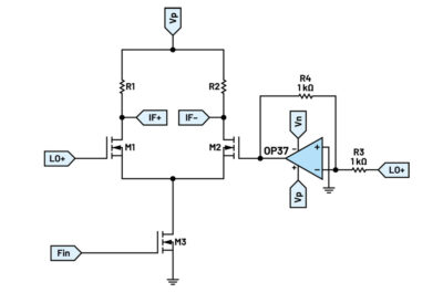 Mieszacze aktywne – ćwiczenie z serii ADALM