
[PROJEKT] KAmodQTR8A + KAmduino UNO – wykrywanie linii dla robotów Linefollower

Moduł KAmodQTR8A to czujnik do wykrywania linii lub przepaści dla robotów klasy Linefollower. Został zbudowany w oparciu o 8 transoptorów odbiciowych KTIR0711S. Informacja o wykrytej powierzchni, z każdego transoptora jest w postaci analogowej. Układ wykrywający linię w konstrukcji typu Linefollower powinien mieć możliwość pomiaru wartości napięcia sygnału, którego to wartość jest proporcjonalna do powierzchni odbijającej światło podczerwone. Jest to zadanie dla typowego przetwornika ADC (ang. Analog to Digital Converter). Drugim sposobem na wykrycie linii z użyciem naszego modułu jest zastosowanie komparatorów (po jednym do każdego czujnika) z dobranymi nastawami przełączania stanu niskiego na wysoki i odwrotnie. Listwa została tak zaprojektowana, aby z łatwością dało się odłamać dwa z ośmiu czujników i użyć ich w innej konfiguracji.
Podczas montażu czujnika w robocie należy zwrócić uwagę na wysokość montażu listwy z czujnikami nad podłożem. Zalecana odległość czujnika od podłoża to 6 mm. Dodatkowo zaleca się osłonięcie czujnika przed wpływem światła zewnętrznego, mogącego doświetlać badaną przez czujniki powierzchnię. Daje to o wiele lepszy efekt działania czujników. W module zostały przewidziane otwory montażowe o średnicy 3 mm. Zarówno przy części „odłamywanej”, jak i przy pozostałych 6 czujnikach. Wymiary modułu (bez złączy) to: 75 mm x 13 mm x 3,2 mm.
Moduł można zasilać napięciem 3,3 V oraz 5 V. Przy zasilaniu napięciem 3,3 V wymagane jest założenie zworki BYPASS. Moduł pobiera prąd o wartości około 90 mA.

Poniższy przykładowy program pozwala na sprawdzenie poprawności montażu i działania czujników na robocie. Konstrukcja testowa została wykonana z płytki prototypowej do której została zamocowana listwa z czujnikami. Wartości napięć zwracanych przez transoptory mierzone są za pomocą przetwornika ADC wbudowanego w mikrokontroler ATmega328 z płytki KAmduino UNO.

Fot. 2. Układ testowy z modułem KAmodQTR8A i KAmduino UNO
Program wykorzystuje bibliotekę QTRSensors.h do kalibracji i odczytywania parametrów powierzchni. Przez pierwsze 10 sekund program wykonuje kalibrację każdego z podłączonych czujników i określa maksymalną oraz minimalną odczytaną wartość. Po wyświetleniu danych kalibracyjnych program przechodzi do pobierania wartości z czujników oraz wyświetlenia ich w postaci danych RAW (surowych i nie obrobionych żadnym algorytmem) w terminalu programu Arduino.
Test polegał na przesuwaniu układu testowego po kartce z namalowaną linią koloru czarnego. Na rysunku 3 widać kolejne zarejestrowane zmiany przemieszczenia układu. Wartość 0 reprezentuje kolor tła w tym przypadku biały, natomiast 1000 oznacza wykrycie czarnej linii.
#include <QTRSensors.h>

// This example is designed for use with six QTR-1A sensors or the first six sensors of a
// QTR-8A module.  These reflectance sensors should be connected to analog inputs 0 to 5.
// The QTR-8A's emitter control pin (LEDON) can optionally be connected to digital pin 2,
// or you can leave it disconnected and change the EMITTER_PIN #define below from 2 to
// QTR_NO_EMITTER_PIN.

// The setup phase of this example calibrates the sensor for ten seconds and turns on
// the LED built in to the Arduino on pin 13 while calibration is going on.
// During this phase, you should expose each reflectance sensor to the lightest and
// darkest readings they will encounter.
// For example, if you are making a line follower, you should slide the sensors across the
// line during the calibration phase so that each sensor can get a reading of how dark the
// line is and how light the ground is.  Improper calibration will result in poor readings.
// If you want to skip the calibration phase, you can get the raw sensor readings
// (analog voltage readings from 0 to 1023) by calling qtra.read(sensorValues) instead of
// qtra.readLine(sensorValues).

// The main loop of the example reads the calibrated sensor values and uses them to
// estimate the position of a line.  You can test this by taping a piece of 3/4" black
// electrical tape to a piece of white paper and sliding the sensor across it.  It
// prints the sensor values to the serial monitor as numbers from 0 (maximum reflectance)
// to 1000 (minimum reflectance) followed by the estimated location of the line as a number
// from 0 to 5000.  1000 means the line is directly under sensor 1, 2000 means directly
// under sensor 2, etc.  0 means the line is directly under sensor 0 or was last seen by
// sensor 0 before being lost.  5000 means the line is directly under sensor 5 or was
// last seen by sensor 5 before being lost.


#define NUM_SENSORS             6  // number of sensors used
#define NUM_SAMPLES_PER_SENSOR  4  // average 4 analog samples per sensor reading
#define EMITTER_PIN             2  // emitter is controlled by digital pin 2

// sensors 0 through 5 are connected to analog inputs 0 through 5, respectively
QTRSensorsAnalog qtra((unsigned char[]) {0, 1, 2, 3, 4, 5},
  NUM_SENSORS, NUM_SAMPLES_PER_SENSOR, EMITTER_PIN);
unsigned int sensorValues[NUM_SENSORS];


void setup()
{
  delay(500);
  pinMode(13, OUTPUT);
  digitalWrite(13, HIGH);    // turn on Arduino's LED to indicate we are in calibration mode
  for (int i = 0; i < 400; i++)  // make the calibration take about 10 seconds
  {
    qtra.calibrate();       // reads all sensors 10 times at 2.5 ms per six sensors (i.e. ~25 ms per call)
  }
  digitalWrite(13, LOW);     // turn off Arduino's LED to indicate we are through with calibration

  // print the calibration minimum values measured when emitters were on
  Serial.begin(9600);
  for (int i = 0; i < NUM_SENSORS; i++)
  {
    Serial.print(qtra.calibratedMinimumOn[i]);
    Serial.print(' ');
  }
  Serial.println();

  // print the calibration maximum values measured when emitters were on
  for (int i = 0; i < NUM_SENSORS; i++)
  {
    Serial.print(qtra.calibratedMaximumOn[i]);
    Serial.print(' ');
  }
  Serial.println();
  Serial.println();
  delay(1000);
}


void loop()
{
  // read calibrated sensor values and obtain a measure of the line position from 0 to 5000
  // To get raw sensor values, call:
  //  qtra.read(sensorValues); instead of unsigned int position = qtra.readLine(sensorValues);
  unsigned int position = qtra.readLine(sensorValues);

  // print the sensor values as numbers from 0 to 1000, where 0 means maximum reflectance and
  // 1000 means minimum reflectance, followed by the line position
  for (unsigned char i = 0; i < NUM_SENSORS; i++)
  {
    Serial.print(sensorValues[i]);
    Serial.print('\t');
  }
  Serial.println(); // uncomment this line if you are using raw values
  //Serial.println(position); // comment this line out if you are using raw values

  delay(250);
}

Rys. 3. Efekt działania programu
 Fotowoltaika perowskitowa: od wydajności laboratoryjnej do masowej komercjalizacji
 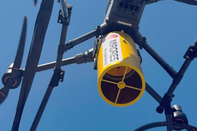 Czy kamery termowizyjne pokazują nam całą prawdę?
 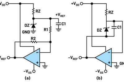 Generowanie ujemnego napięcia odniesienia – eksperymenty z zestawem ADALM2000

![O konkursie organizowanym przez firmę TRUMPF Huettinger i polskie uczelnie techniczne opowiada Alicja Peresada i prof. Jacek Rąbkowski oraz kilkoro nagrodzonych dyplomantów: mgr inż. Jakub Dobosz, inż. Maja Zielińska, dr inż. Jakub Kołodziej, dr inż Weronika Hryniewska-Guzik i dr inż. Grzegorz Bartyzel. Zapraszamy do obejrzenia filmu! [materiał redakcyjny]](https://mikrokontroler.pl/wp-content/uploads/2026/07/TRUMPF-czolowka.png "https://www.youtube.com/watch?v=XkeyLmtLfxo")